- 您现在的位置:买卖IC网 > Sheet目录2004 > LTC1458LIG#TRPBF (Linear Technology)IC D/A CONV 12BIT R-R QUAD28SSOP
4
LTC1458/LTC1458L
Note 1: Absolute Maximum Ratings are those values beyond which the life
of a device may be impaired.
Note 2: Nonlinearity is defined from the first code that is greater than or
equal to the maximum offset specification to code 4095 (full scale).
Note 3: Load is 5k
in parallel with 100pF.
Note 4: DAC switched between all 1s and the code corresponding to VOS
for the part.
Note 5: Digital inputs at 0V or VCC.
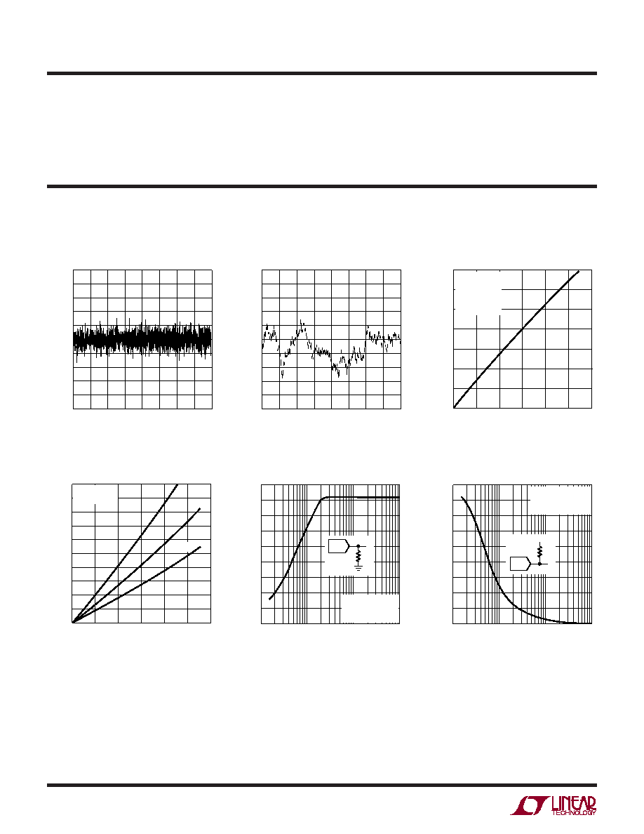
LTC1458
Integral Nonlinearity (INL)
LTC1458
Differential Nonlinearity (DNL)
CODE
0
DNL
(LSB)
0.5
0.4
0.3
0.2
0.1
0
–0.1
–0.2
–0.3
–0.4
–0.5
1024
2048 2560
1458 G09
512
1536
3072 3584 4095
CODE
0
INL
ERROR
(LSB)
2.0
1.6
1.2
0.8
0.4
0
–0.4
–0.8
–1.2
–1.6
–2.0
1024
2048 2560
1458 G08
512
1536
3072 3584 4095
Minimum Supply Headroom for
Full Output Swing vs Load Current
LOAD CURRENT (mA)
V
CC
–
V
OUT
(V)
1.4
1.2
1.0
0.8
0.6
0.4
0.2
0
1458 G03
0
VOUT < 1LSB
REFLO = GND
X1/X2 = GND
CODE: ALL 1's
VOUT = 4.095V
5
10
15
20
25
30
Minimum Output Voltage vs
Output Sink Current
Output Swing vs Load Resistance
LOAD RESISTANCE (
)
10
OUTPUT
SWING
(V)
4.5
4.0
3.5
3.0
2.5
2.0
1.5
1.0
0.5
0
100
1k
10k
1458 G05A
RL
REFLO = GND
X1/X2 = GND
DAC CODE = FFFH
LOAD RESISTANCE (
)
10
OUTPUT
SWING
(V)
4.5
4.0
3.5
3.0
2.5
2.0
1.5
1.0
0.5
0
100
1k
10k
1458 G06A
REFLO = GND
X1/X2 = GND
DAC CODE = OOOH
RL
VCC
OUTPUT SINK CURRENT (mA)
OUTPUT
PULL-DOWN
VOLTAGE
(mV)
1000
900
800
700
600
500
400
300
200
100
0.1
1458 G04
0
REFLO = GND
X1/X2 = GND
125
°C
–55
°C
25
°C
5
10
15
20
25
30
Output Swing vs Load Resistance
ELECTRICAL CHARACTERISTICS
TYPICAL PERFOR A CE CHARACTERISTICS
UW
发布紧急采购,3分钟左右您将得到回复。
相关PDF资料
LTC1482CMS8
IC TXRX RS485 LOWPWR 8-MSOP
LTC1484IS8#TRPBF
IC TXRX RS485 LOWPWR 8-SOIC
LTC1518IS#TRPBF
IC LINE RCVR RS485 QUAD 16-SOIC
LTC1543IG#TRPBF
IC TXRX SOFTWARE SELECTBL 28SSOP
LTC1544IG#TRPBF
IC TXRX SOFTWARE SELECTBL 28SSOP
LTC1545CG
IC TXRX SOFTWARE SELECTBL 36SSOP
LTC1590IS#TRPBF
IC D/A CONV 12BIT DUAL 16-SOIC
LTC1592AIG#TRPBF
IC D/A CONV 16BIT SOFTSPAN16SSOP
相关代理商/技术参数
LTC1458LISW
功能描述:IC D/A CONV 12BIT R-R QUAD28SOIC RoHS:否 类别:集成电路 (IC) >> 数据采集 - 数模转换器 系列:- 产品培训模块:Data Converter Fundamentals
DAC Architectures 标准包装:750 系列:- 设置时间:7µs 位数:16 数据接口:并联 转换器数目:1 电压电源:双 ± 功率耗散(最大):100mW 工作温度:0°C ~ 70°C 安装类型:表面贴装 封装/外壳:28-LCC(J 形引线) 供应商设备封装:28-PLCC(11.51x11.51) 包装:带卷 (TR) 输出数目和类型:1 电压,单极;1 电压,双极 采样率(每秒):143k
LTC1458LISW#PBF
功能描述:IC D/A CONV 12BIT R-R QUAD28SOIC RoHS:是 类别:集成电路 (IC) >> 数据采集 - 数模转换器 系列:- 标准包装:2,400 系列:- 设置时间:- 位数:18 数据接口:串行 转换器数目:3 电压电源:模拟和数字 功率耗散(最大):- 工作温度:-40°C ~ 85°C 安装类型:表面贴装 封装/外壳:36-TFBGA 供应商设备封装:36-TFBGA 包装:带卷 (TR) 输出数目和类型:* 采样率(每秒):*
LTC1458LISW#TR
功能描述:IC DAC 12BIT R-R 3V QUAD 28SOIC RoHS:否 类别:集成电路 (IC) >> 数据采集 - 数模转换器 系列:- 产品培训模块:Data Converter Fundamentals
DAC Architectures 标准包装:750 系列:- 设置时间:7µs 位数:16 数据接口:并联 转换器数目:1 电压电源:双 ± 功率耗散(最大):100mW 工作温度:0°C ~ 70°C 安装类型:表面贴装 封装/外壳:28-LCC(J 形引线) 供应商设备封装:28-PLCC(11.51x11.51) 包装:带卷 (TR) 输出数目和类型:1 电压,单极;1 电压,双极 采样率(每秒):143k
LTC1458LISW#TRPBF
功能描述:IC D/A CONV 12BIT R-R QUAD28SOIC RoHS:是 类别:集成电路 (IC) >> 数据采集 - 数模转换器 系列:- 标准包装:2,400 系列:- 设置时间:- 位数:18 数据接口:串行 转换器数目:3 电压电源:模拟和数字 功率耗散(最大):- 工作温度:-40°C ~ 85°C 安装类型:表面贴装 封装/外壳:36-TFBGA 供应商设备封装:36-TFBGA 包装:带卷 (TR) 输出数目和类型:* 采样率(每秒):*
LTC1470CS8
功能描述:IC SWTCH PCMCIA3.3V/5V SNGL8SOIC RoHS:否 类别:集成电路 (IC) >> PMIC - 电源分配开关 系列:- 特色产品:XRP252 Switches 标准包装:1 系列:- 类型:高端开关 输出数:2 Rds(开):140 毫欧 内部开关:是 电流限制:1.15A 输入电压:1.75 V ~ 5.5 V 工作温度:-40°C ~ 85°C 安装类型:表面贴装 封装/外壳:10-WFDFN 裸露焊盘 供应商设备封装:10-TDFN(3x3) 包装:Digi-Reel® 其它名称:1016-1691-6
LTC1470CS8#PBF
功能描述:IC SWTCH PCMCIA3.3V/5V SNGL8SOIC RoHS:是 类别:集成电路 (IC) >> PMIC - 电源分配开关 系列:- 标准包装:80 系列:- 类型:USB 开关 输出数:2 Rds(开):135 毫欧 内部开关:是 电流限制:1.5A 输入电压:2.7 V ~ 5.5 V 工作温度:-40°C ~ 85°C 安装类型:表面贴装 封装/外壳:8-TSSOP,8-MSOP(0.118",3.00mm 宽)裸露焊盘 供应商设备封装:8-MSOP-PowerPad 包装:管件 配用:TPS2066-1EVM-296-ND - TPS2066-1EVM-296
LTC1470CS8#TR
功能描述:IC MATRIX SW SINGLE 5/3.3V 8SOIC RoHS:否 类别:集成电路 (IC) >> PMIC - 电源分配开关 系列:- 特色产品:XRP252 Switches 标准包装:1 系列:- 类型:高端开关 输出数:2 Rds(开):140 毫欧 内部开关:是 电流限制:1.15A 输入电压:1.75 V ~ 5.5 V 工作温度:-40°C ~ 85°C 安装类型:表面贴装 封装/外壳:10-WFDFN 裸露焊盘 供应商设备封装:10-TDFN(3x3) 包装:Digi-Reel® 其它名称:1016-1691-6
LTC1470CS8#TRPBF
功能描述:IC SWTCH PCMCIA3.3V/5V SNGL8SOIC RoHS:是 类别:集成电路 (IC) >> PMIC - 电源分配开关 系列:- 特色产品:XRP252 Switches 标准包装:1 系列:- 类型:高端开关 输出数:2 Rds(开):140 毫欧 内部开关:是 电流限制:1.15A 输入电压:1.75 V ~ 5.5 V 工作温度:-40°C ~ 85°C 安装类型:表面贴装 封装/外壳:10-WFDFN 裸露焊盘 供应商设备封装:10-TDFN(3x3) 包装:Digi-Reel® 其它名称:1016-1691-6